Apple MacBook Pro 16" 2021 A2485 M1/M1 Max Logic Board - Best Logic Board Repair
https://moverapple.com/products/apple-macbook-pro-16-2021-m1-m1-max-logic-board-best-logic-board-repair?VariantsId=10132 VIDEO
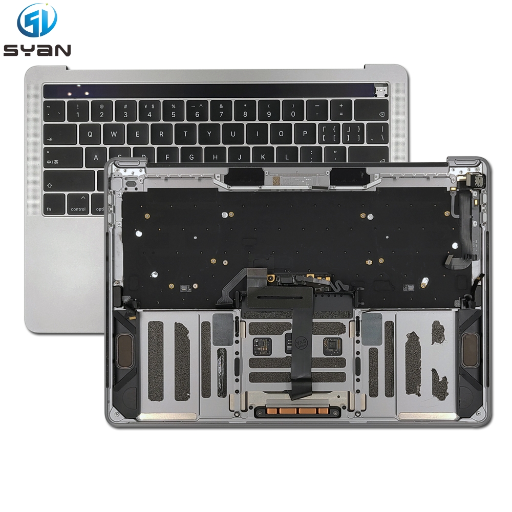
MacBook Pro 16-inch (M1, 2021, A2485) Logic Board Replacement Guide
This step-by-step guide teaches you how to safely remove and install the logic board (motherboard) on the MacBook Pro 16-inch Retina (M1, 2021, Model A2485) . It is optimized for search engines and DIY repairers.
Overview
Model Compatibility : MacBook Pro 16-inch Retina, M1 Pro/Max, 2021, A2485Difficulty : Advanced (requires precision and care with fragile cables)Estimated Time : 2.5–4 hoursKey Risk : Damage to flex cables, connectors, or the battery (always disconnect the battery first )
Tools Required
Gather these tools before starting:
T5 Torx screwdriver (for bottom case screws)
T6 Torx screwdriver (for logic board/heat sink screws)
3IP Torx screwdriver (for connector cowlings)
Plastic spudger (non-conductive, for prying cables/connectors)
Tweezers (fine-tipped, for cable handling)
Anti-static wrist strap (critical to prevent ESD damage)
Isopropyl alcohol + microfiber cloth (for cleaning)
Magnetic screw mat (to organize screws by length/location)
Safety Precautions
ESD Protection : Wear an anti-static wrist strap and work on a grounded, static-free mat. Static electricity can destroy the logic board.Battery Safety : The lithium-ion battery is highly flammable if punctured or bent . Never pry or twist the battery.Cable Care : All flex cables (display, keyboard, fans, etc.) are thin and tear easily. Pull parallel to the connector, never upward.Power Off Completely : Shut down the MacBook, unplug all peripherals, and disconnect the power adapter before opening the case.
Step 1: Remove the Bottom Case
Place the MacBook upside-down on a soft, non-slip surface (e.g., a microfiber cloth).
Use a T5 Torx screwdriver to remove the 10 bottom case screws :
6 × 3.8 mm screws
4 × 4.6 mm screws
Note: Keep screws organized on a magnetic mat—lengths vary by position.
Insert a plastic spudger into the gap between the bottom case and the aluminum frame. Gently pry upward to release the clips.
Work your way around the edges (left → top → right) until all clips are released. Lift the bottom case straight up and set it aside.
Step 2: Disconnect the Battery (Critical!)
Locate the battery connector (a wide black flex cable) on the left side of the logic board.
Use a plastic spudger to gently lift the locking flap on the ZIF connector.
Pull the battery flex cable straight out of the connector. Never yank the cable—this will tear the wires.
Confirm the battery is fully disconnected before proceeding.
Step 3: Remove Connector Cowlings
The A2485 has 10 metal connector cowlings protecting flex cable connectors. Remove them in this order:
Left/Right Speaker Cowlings : 2 × 3IP screws each (4 total)MagSafe 3 Board Cowling : 2 × 3IP screwsLid Angle Sensor Cowling : 2 × 3IP screwsLeft USB-C Board Cowlings : 2 × 3IP screwsTouch ID/Display Connector Cowlings : 2 × 3IP screws
Use a 3IP Torx screwdriver to remove all screws.
Lift each cowling straight up and set it aside (note orientation for reassembly).
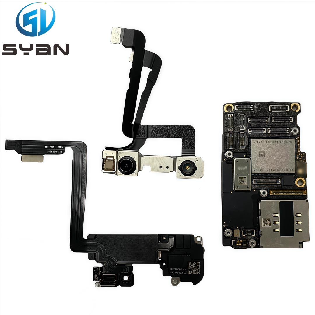
Step 4: Disconnect All Flex Cables from the Logic Board
Disconnect cables one at a time to avoid confusion. Use tweezers or a spudger for delicate connectors:
Lid Angle Sensor Flex Cable (top-left)MagSafe 3 Flex Cable (next to sensor)Left USB-C Board Flex Cables (2 cables)Audio Board Flex Cable (left of fans)Left/Right Speaker Flex Cables (2 cables)Display Flex Cable (top-right, large cable)Keyboard Flex Cable (bottom-center)Keyboard Backlight Flex Cable (below keyboard)Left/Right Fan Flex Cables (2 cables, near fans)
For ZIF connectors : Lift the plastic locking flap up, then pull the cable out.
For press-fit connectors : Gently pry upward with a spudger (avoid bending the cable ).
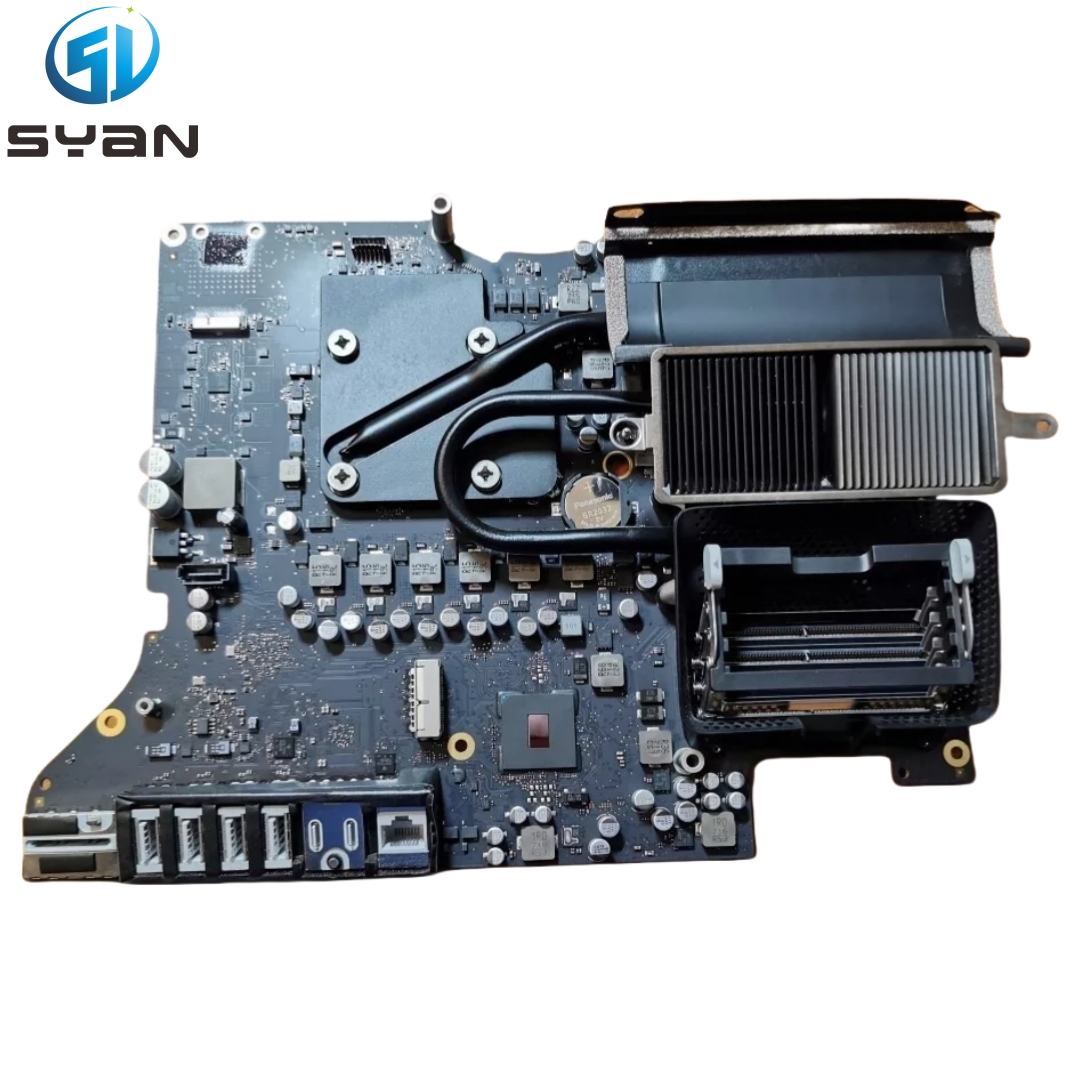
Step 5: Disconnect Fans and Heat Sink
Right Fan : Peel back any adhesive tape. Lift the ZIF locking flap and disconnect the fan cable. Repeat for the Left Fan .
Heat Sink Screws : Use a T6 Torx screwdriver to remove the 2 × 6 mm screws securing the heat sink to the logic board and frame.
The heat sink is attached to the logic board with thermal paste—do not force it off yet.
Step 6: Remove Logic Board Mounting Screws
Use a T5 Torx screwdriver to remove the 12 logic board mounting screws :
6 × 3.9 mm screws (outer edges)
4 × 4.7 mm screws (inner frame)
2 × 6 mm hex screws (front edge, near USB-C ports)
Keep screws organized—they are not interchangeable.
Step 7: Release and Remove the Logic Board
Release Clips : Insert a plastic spudger between the right side of the logic board and the frame. Gently pry upward to release the plastic clips.
Repeat for the bottom edge of the logic board to release additional clips.
Lift the Board : Gently lift the right side of the logic board first, then tilt it upward to clear the alignment pegs.
Pull Away : Slide the logic board to the left to separate the HDMI and SDXC ports from the frame slots.
Lift the logic board straight up and out of the MacBook. Place it on an anti-static mat.
Step 8: Transfer Components to the New Logic Board (If Needed)
If your new logic board does not include the heat sink or thermal pads:
Remove Heat Sink : Gently twist the heat sink to break the thermal paste seal. Lift it off the old logic board.Clean Thermal Paste : Use isopropyl alcohol and a microfiber cloth to remove all old thermal paste from the heat sink and logic board.Apply New Thermal Paste : Add a small pea-sized dot of thermal paste to the center of the new logic board’s CPU/GPU area.Reattach Heat Sink : Align the heat sink with the new logic board and tighten the T6 screws evenly (alternate sides to avoid bending).
Step 9: Install the New Logic Board
Align the Board : Hold the new logic board at a slight angle. Insert the left side first, then lower the right side into the frame.
Secure Clips : Press down firmly on the right and bottom edges to snap the logic board into the plastic clips.Reinstall Mounting Screws : Replace all 12 logic board screws (T5 Torx) in their original positions. Tighten them snugly (do not over-tighten).
Step 10: Reconnect All Flex Cables
Reverse the disconnection order from Step 4 :
Connect fan cables → keyboard backlight → keyboard → display → speakers → audio → USB-C → MagSafe → lid angle sensor.
For ZIF connectors: Insert the cable straight into the slot, then press the locking flap down to secure.
For press-fit connectors: Align the cable and press down gently until it clicks into place.
Step 11: Reinstall Connector Cowlings
Align each metal cowling in its original orientation (markings face up).
Replace all 3IP screws (10 cowlings, 2 screws each). Tighten them evenly.
Step 12: Reconnect the Battery
Align the battery flex cable with the ZIF connector on the logic board.
Insert the cable straight in , then press the locking flap down to secure.
Confirm the connection is tight—no loose cables.
Step 13: Reattach the Bottom Case
Align the bottom case with the MacBook frame. Press down firmly around the edges to snap the clips into place.
Replace all 10 T5 Torx screws (6 × 3.8 mm, 4 × 4.6 mm). Tighten them evenly.
Step 14: Test the MacBook
Connect the power adapter and press the power button.
Verify the MacBook boots up normally.
Test all functions: display, keyboard, trackpad, USB-C ports, speakers, Wi-Fi, and Bluetooth.
If any issues occur, power off and recheck all cable connections.
Troubleshooting Common Issues
No Power : Recheck the battery connection and ensure all logic board screws are tight.Display Black : Verify the display flex cable is fully inserted and locked.Fans Not Spinning : Reconnect the fan cables and check for pinched wires.USB-C Not Working : Ensure the USB-C board flex cables are properly seated.
Final Notes
Warranty : Replacing the logic board may void your Apple warranty. Proceed at your own risk.Genuine Parts : Use only genuine Apple or high-quality third-party logic boards to avoid compatibility issues.ESD Safety : Always store the old logic board in an anti-static bag to prevent damage during transport.