How to Replace Logic Board on 27" iMac Pro A1862
iMac Pro A1862 logic board replacement, iMacPro1,1 mainboard swap guide, 820-00967-A logic board install, iMac Pro A1862 teardown, fix iMac Pro no boot, iMac Pro motherboard replacement, Late 2017 iMac Pro logic board repair
Model: 27-inch iMac Pro A1862
Model Identifier: iMacPro1,1
Release: Late 2017 | EMC 3144
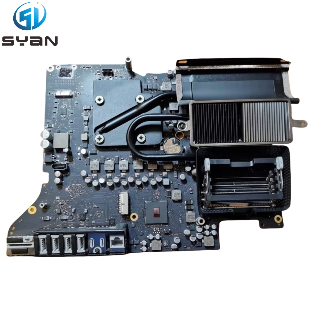
Board part numbers covered: 820-00967-A, 820-00976-09
CPU: Intel Xeon W series (W-2140B / W-2145 / W-2150B / W-2155)
GPU: Radeon Pro Vega 56 / Vega 64 / Vega 64X
RAM: Soldered onboard RAM, cannot swap separately
SSD: Custom Apple iMac Pro SSD module
⚠️ Important Pre-Repair Warnings (high intent search section)
- This is an advanced Apple desktop repair. If you lack iMac teardown experience, send it to a professional Mac repair shop.
- Fully shut down the iMac Pro, unplug the AC power cord. Wait 10 minutes for PSU high-voltage capacitors to discharge to avoid electric shock.
- Static electricity will destroy the logic board. Always use an anti-static wrist strap and anti-static mat.
- Back up all data before disassembly. Turn off Find My Mac before swapping the logic board if possible.
- Take clear photos of every cable and connector before disconnecting for reference during reassembly.
- Required repair tools: Suction cups, plastic pry picks, Torx T3, T4, T5, T8 screwdrivers, tweezers, new iMac display adhesive tape.
Step-by-Step Logic Board Replacement Instructions
Step 1: Remove front glass panel
Attach suction cups firmly to the front glass. Slowly peel the glass away from the adhesive seal. Disconnect the camera and microphone flex ribbon cables, then set the glass panel somewhere safe.
Step 2: Remove the LCD screen assembly
Unscrew all Torx fasteners securing the LCD panel. Carefully disconnect the eDP display cable and LCD backlight cable. Lift the LCD out slowly, place it face-up on a soft non-scratch surface. Be careful not to bend or crack the LCD.
Step 3: Disconnect all cables linked to the logic board
Disconnect these connectors one by one:
- 4 power terminals from the power supply to logic board
- Apple SSD module ribbon
- Thunderbolt 3 / I/O flex cables
- Wi‑Fi / Bluetooth antenna coax cables
- System fan connectors
- Temperature sensor ribbons
- Speaker cables, headphone jack cable
Label or photograph every connector to avoid mix-up.
Step 4: Remove CPU/GPU heatsink assembly
Unscrew the Torx T8 heatsink mounting screws. Loosen the heatsink evenly to prevent PCB warping. Lift the heatsink off the logic board. Clean old thermal paste off the heatsink; reapply fresh thermal paste before reinstallation.
Step 5: Uninstall the old faulty logic board
Remove all Torx T8 mounting screws holding the logic board to the rear chassis. Gently lift the old logic board out of the chassis. Avoid scraping the aluminum shell or tearing leftover flex cables.
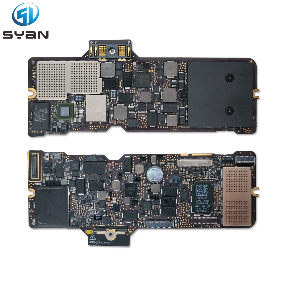
Step 6: Install replacement pulled logic board (820-00967-A / 820-00976-09)
Align the replacement logic board into the chassis mounting points. Hand-thread all Torx screws, then torque them evenly.
Do not over-tighten screws — over-torque can crack the PCB.Step 7: Reinstall heatsink and reapply thermal paste
Add a thin, even layer of thermal paste on the Xeon CPU and Vega GPU die. Seat the heatsink, fasten screws in a cross pattern for even pressure.
Step 8: Reconnect all internal cables and antenna wires
Reconnect PSU power terminals, SSD ribbon, antenna coax, fan cables, temperature sensors and all flex connectors. Double-check every connector is fully seated and locked. Bent pins or loose cables cause no boot, black screen or overheating.
Step 9: Reinstall LCD panel
Reconnect the eDP display cable and backlight cable. Carefully place the LCD back into the chassis and fasten all LCD mounting screws.
Step 10: Reattach front glass with new adhesive tape
Apply fresh double-sided iMac display adhesive tape on the chassis rim. Reconnect camera and microphone ribbons, then press the glass panel into position. Press firmly along the seal for proper adhesion.
Step 11: Power on and full function testing
Plug in the AC cord and power on the iMac Pro. Test boot sequence, screen output, Thunderbolt 3 ports, USB, Ethernet, Wi-Fi, Bluetooth, audio, fan speed regulation and GPU graphics performance.
✅ Success: Boots normally and all ports / features work
❌ Troubleshooting checklist:
- Black screen: Recheck eDP and backlight cables
- No boot: Inspect SSD module and PSU power terminals
- Fan runs full blast constantly: Temperature sensor cable disconnected
- Kernel panic / unstable boot: Reset SMC and NVRAM
FAQ Section (High Search Volume Questions)
Q: Can I upgrade CPU or GPU by swapping this A1862 logic board?
A: CPU and GPU are soldered to the logic board. The specs are fixed on the board you install.
Q: Do I need firmware programming after logic board swap?
A: Pre-tested OEM pulled boards usually do not require re-flashing. If boot loops happen, restore firmware with Apple Configurator 2 on a second Mac.
Q: Will my original A1862 SSD work on this replacement logic board?
A: Yes, the factory iMac Pro SSD module is reusable, data can remain intact.
Q: Is this tutorial suitable for other iMac models?
A: No, this guide only applies to A1862 iMac Pro Late 2017. It does NOT fit A1419, A2115, M1/M3 iMac or Mac Pro tower.